Application of Infrared Thermal Imaging Camera for PCB Circuit Board Test
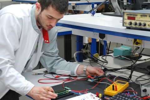
The word temperature affects both the service life and validity of electronic equipment. The circuit board needs extensive testing for full functionality. This is expedient in order to ensure the guaranteed and optimal functioning of products. Another vital point to note is that features such as the thermal design, selection of parts, the production process and Human Resource greatly impact the power circuit heating dissipation.
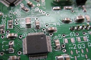
HEATING OF THE PCB CIRCUIT BOARD
There are numerous factors responsible for the heating of the circuit board such as the tendency for the wires to become resistant thereby fostering the heating up of the circuit board. In the same vein, how much power the component can carry is a determinant factor in the heating process. For instance, there will be a level of power issues if the ability of a component is small, this causes the device to heat up and then the heat is dissipated to the circuit board. Another important factor is the challenge of the dissipation of heat and power consumption capacity. The range of the full consumption of power by the circuit board is so little. The normal range for the power capacity of the circuit board is expected to be 2.5-3 times of the overall consumption of power. The need for a cooling fan is expedient. Another challenge can present itself in the form of the Layout which can attribute to the state in which the dissipation occurred and the ambient environment of the circuit board. In the event that the circuit board is in close proximity with another device that releases heat and there is no room for proper ventilation and then the circuit board has been sealed, what follows is the accumulation of heat which in turn makes the circuit board overheat. We should consider the design of the circuit board. How this factor affects the functionality of the circuit board is explanatory. A circuit board that has unnecessary high current lines will not function well. For instance, copper foil has a current-carrying capacity which is smaller than 3 Amps/mm2. Lastly, we would like to also consider other typical challenges such as poor interphase, faulty parts or units, short circuit and so on.
CUSTOMERS REQUIRE SOLUTION TO THE FOLLOWING CHALLENGES:
- There is a need for an organized arrangement or better put layout of the components. The reason for this is because high-power devices are known for releasing a high level of heat. However, the thermal load can be stable if there is an organized arrangement of these various components.
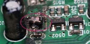
- It is no news that the devices may heat up but what is important is for the exact unit which overheats to be located. This is important so as to prevent the undue failure of the entire circuit board which may be credited to an incorrect selection of device and lengthy operation time.
- Another important challenge is faulty and short welding which plays out in increased cost for customer service.
- The thermal load area will need to be located, then undergo the process of evaluating if the thermal designs have any influence and then developing a plan that will be aimed at full operation. All these will be aimed at totally ensuring that the dissipation of heat is optimized.
PRESENT SOLUTIONS WITH THEIR LIMITATIONS
The following are the solutions that are available but they also come with unique demerits of their own:
ThermoCouple and Data Acquisition (DAQ)
We have what is called ThermoCouple and Data Acquisition (DAQ) with the following shortcoming points;
- The thermocouple does not operate in a non-contact mode with other components. The multichannel DAQ system is used in obtaining the temperature records. Even though the measurement of temperature is reliable but it is rather cumbersome.
- The process takes time and is not in any way efficient to put the thermocouple on other components owing to different laws.
- It is possible that the thermocouple can cause variations in the distribution of heat of components that are of small size.
- There is the possibility of a lag between the temperature recorded and the actual temperature due to the fact that the thermocouple experiences what we simply refer to as temperature inertia.
- The limitation in the number of channels causes the thermocouple to be inserted in just a few places and even this act is solely subject to the expertise of the operator.
- There is a concern for the safety of the operator as some PCBs are known to be carriers of current and voltage that can really pose a great threat.
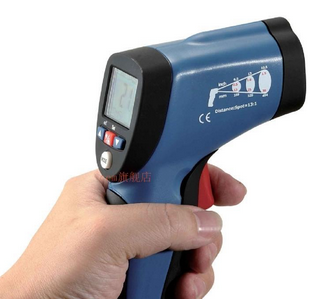
Infrared Thermometer Gun
- The use of the Infrared thermometer is with ease though it poses numerous challenges.
- Variations in temperature cannot be subject to analysis.
- Inability to detect multiple spots simultaneously which in turn leads to poor synchronization of data.
- Poor massive storage of data thereby requiring the old-fashioned style of having to pin down the details.
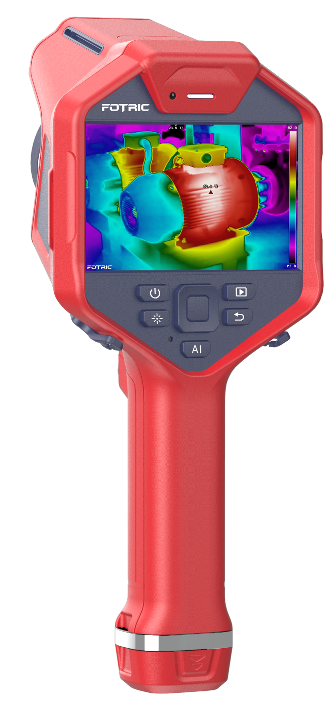
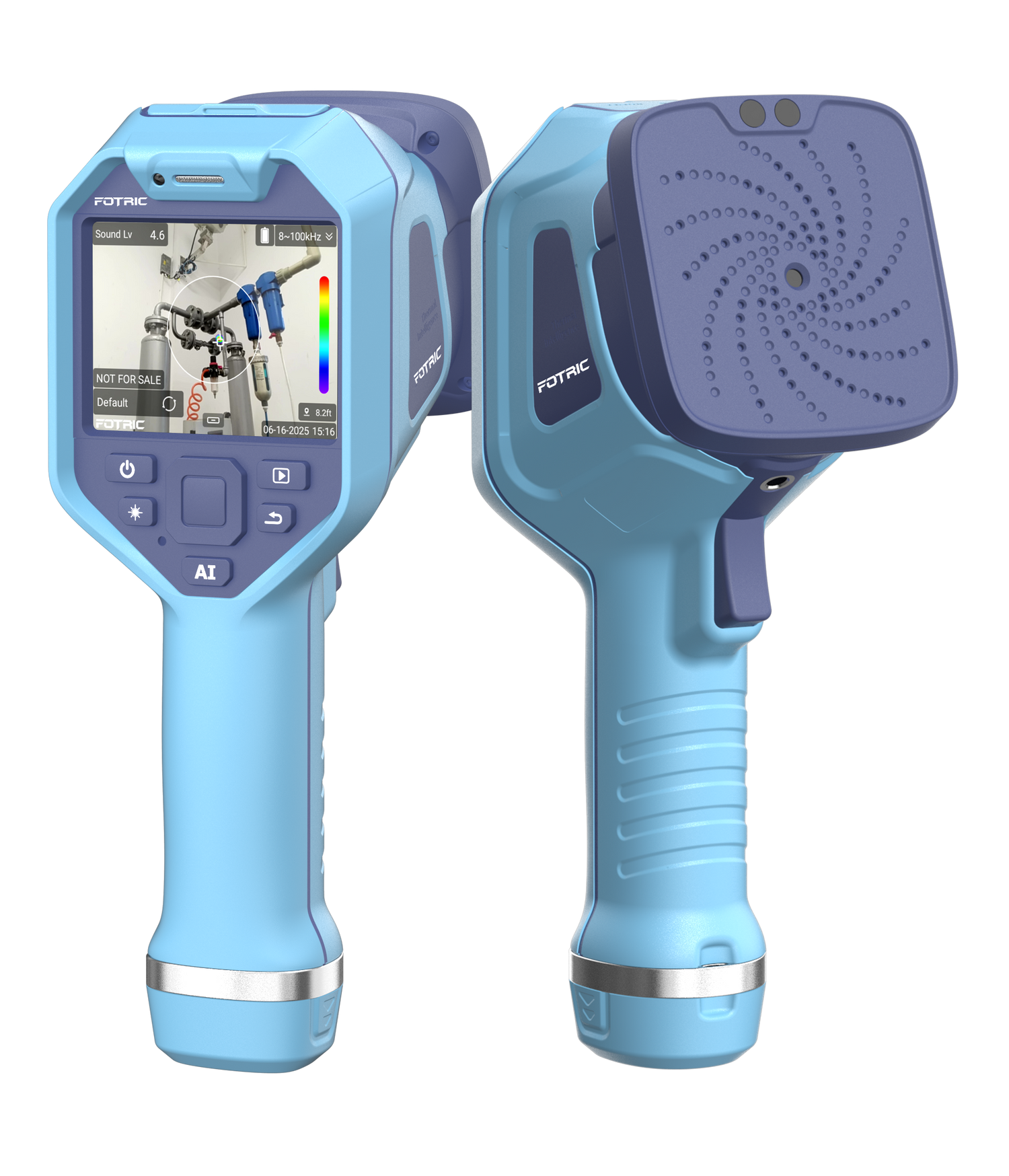
USEFULNESS OF THE FOTRIC 220 SERIES THERMAL CAMERAS
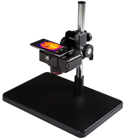
Testbench Test Kit
Fotric 226 infrared thermal imaging camera three-in-one(3-in-1) infrared camera is capable of recording 384x288 (110,592) temperature values. The awesome feature is that this can be achieved on just a single thermal image. The collection and the saving of the whole circuit board can all be done at once. The temperature values can also be generated perfectly by detecting blind spots.
The Radiometric Video Stream and Recording up to 1TB Single Video File
Furthermore, Fotric 226 thermal imager can be attached to a PC and configurations with a professional AnalyzIR can be made so as to monitor the online thermal camera with 110,592 channels DAQ which is useful in recording the total radiometric thermal video streams.
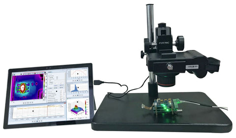
Powerful Multiple Temperature History Analysis Simultaneously
There is provision for real-time measurement of the changes in temperature.

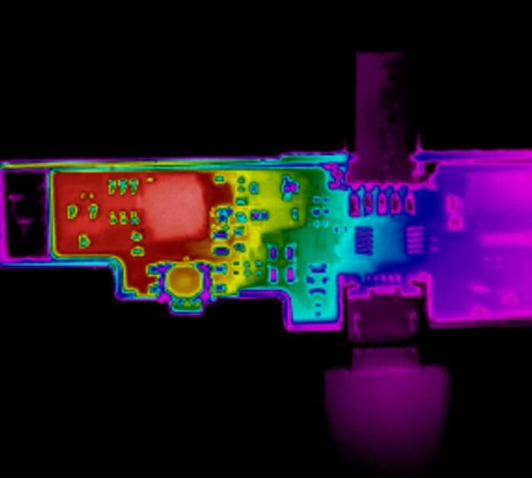
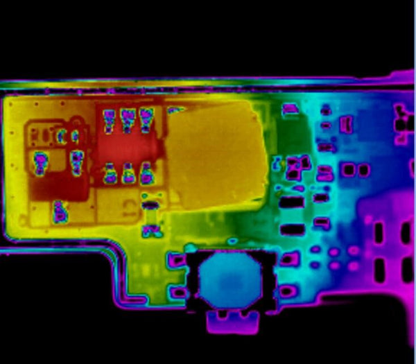
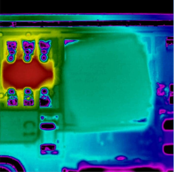
Optional Macro Lens to Help See the Tiny Spots up to 20 Micros
A radiometric thermal image was taken by Fotric standard lens
A radiometric thermal image was taken by Fotric 50 Micron Resolution Macro Close-Up lens
A radiometric thermal image was taken by Fotric 20 Micron Resolution Macro Close-Up lens (with Fotric 228 and M20-228 Macro Lens)
RECOMMENDED THERMAL CAMERA PACKAGE
- Fotric 226 3-in-1 Thermal Camera
- Fotric M50-226 Macro Lens 50 Micron Resolution
- B1 R&D Testbench Platform
OTHER USES
The Fotric thermal camera finds application in the research and development units of consumer electronics which includes but not limited to smartphones, LED, IoT hardware. Also finds usefulness in the R&D departments of industrial electronics establishments which includes power devices, frequency converters, and Energy.
MORE QUESTIONS?
To learn more about FOTRIC infrared thermal imaging cameras, please visit www.NovaTestPro.com or contact info@NovaTestPro.com for any inquiries.